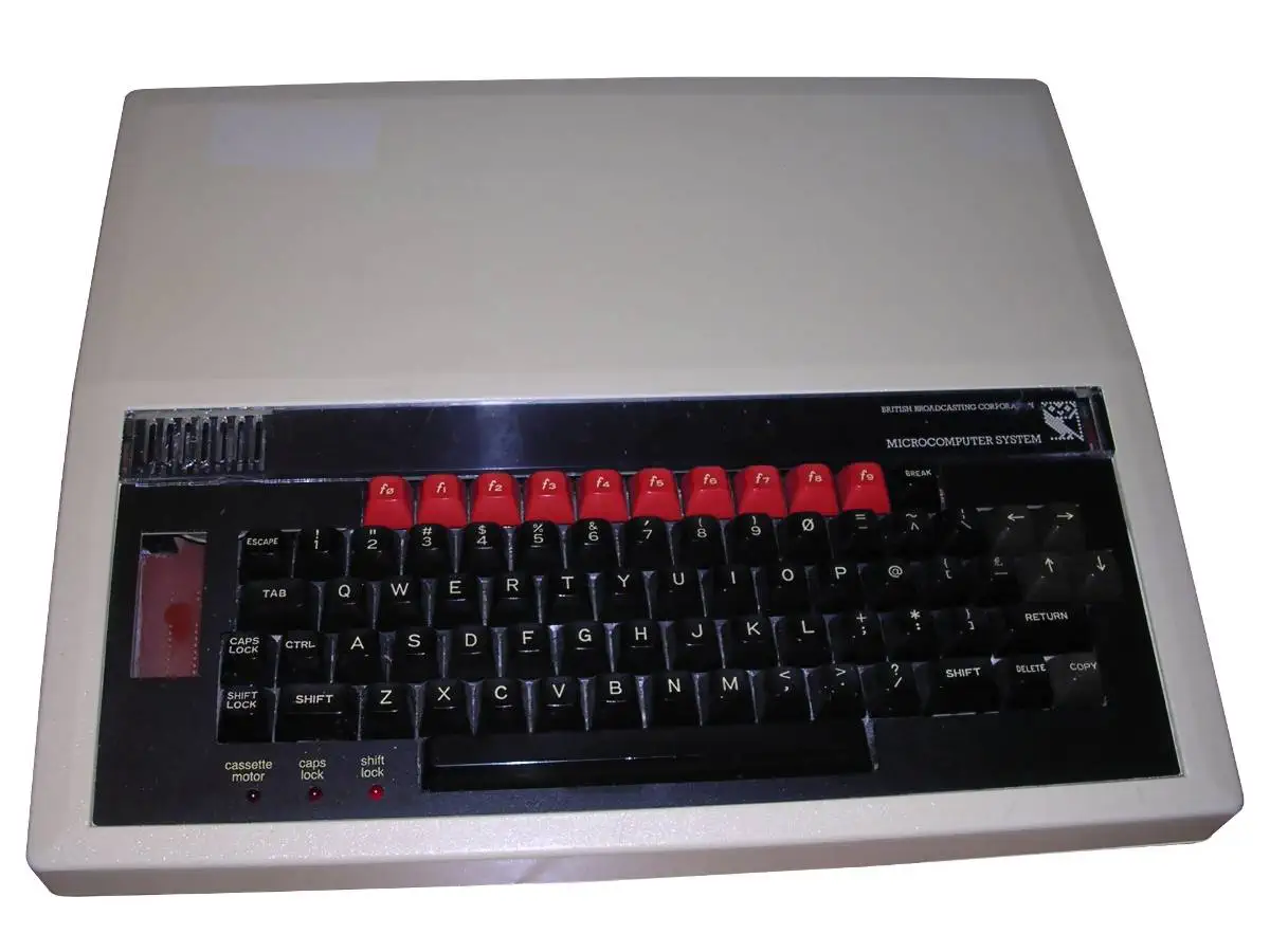

BBC Micro - Model B
The BBC Micro - Model B was an upgrade to the Model A in terms of memory. Other than that the machine was practically identical to the Model A.
During the early 1980s, the BBC started what became known as the BBC Computer Literacy Project. The project was initiated partly in response to an ITV documentary series The Mighty Micro, in which Christopher Evans of the UK's National Physical Laboratory predicted the coming microcomputer revolution and its effect on the economy, industry, and lifestyle of the United Kingdom.
The BBC wanted to base its project on a microcomputer capable of performing various tasks which they could then demonstrate in the TV series The Computer Programme. The list of topics included programming, graphics, sound and music, teletext, controlling external hardware, and artificial intelligence. It developed an ambitious specification for a BBC computer, and discussed the project with several companies including Acorn Computers, Sinclair Research, Newbury Laboratories, Tangerine Computer Systems, and Dragon Data.
The introduction of a specific microcomputer to a more general computer literacy initiative was a topic of controversy, however, with criticism aimed at the BBC for promoting a specific commercial product and for going beyond the "traditional BBC pattern" of promoting existing information networks of training and education providers. Accusations were even levelled at the Department of Industry for making the BBC "an arm of Government industrial policy" and using the Computer Literacy Project as a way of "funding industry through the back door", obscuring public financial support on behalf of a government that was ostensibly opposed to subsidising industry.
Regardles of controversy, the BBC Micro was introduced in 1981 and quickly became the UK education computer of choice.
Three model B systems were created:
- BBC Micro - Model B (32KByte RAM)
- BBC Micro - Model B+64 (64KByte RAM)
- BBC Micro - Model B+128 (128KByte RAM)
The model B motherboard, revision 3 had slight changes compared to the Model A motherboard. Most notable is the change in size of the cooling block in the right middle, which is smaller than the original.
ARM, an acronym for Advanced RISC Machines (originally Acorn RISC Machines) is a Reduced Instruction Set Computer (RISC) cpu architecture.
The first machine that used the ARM chip was the BBC Micro, it used the ARM as a secondary processor at 6MHz. The ARM helped in developing simulation software used to finish the development of other chips such as the VIDC (Video), IOC (I/O) en MEMC (Memory management) chips that were used in later Acorn/BBC machines. At the same time BBC Basic was completely rewritten in ARM assembly language.
BBC Basic Language and OS
BBC BASIC was a high-level programming language created by Acorn Computers in 1981 for the BBC Microcomputer System, commissioned by the BBC Computer Literacy Project. It was based on the earlier Dartmouth BASIC but extended with structured programming features and inline assembler support, making it both beginner-friendly and powerful for advanced users. Unlike many contemporary BASIC dialects, BBC BASIC emphasized readability, supporting named procedures and functions, local variables, and full IF...THEN...ELSE constructs, which helped foster good programming practice among students and hobbyists.
One of the most distinctive aspects of BBC BASIC was its ability to integrate 6502 assembly language directly within BASIC source code. This meant programmers could write performance-critical routines in machine code without leaving the BASIC environment, a feature that was far ahead of its time. Combined with the BBC Micro’s flexible graphics and sound capabilities, BBC BASIC provided a complete toolkit for educational, scientific, and entertainment applications, spanning simple text-based teaching programs to advanced arcade-style games.
BBC BASIC survived long beyond the BBC Micro itself. Versions were ported to CP/M, MS-DOS, RISC OS, Windows, and even modern platforms like iOS and Android through interpreters and emulators. Its legacy lies not only in its technical innovations but also in its cultural impact: an entire generation of UK students learned programming principles through BBC BASIC. Below is a simple code sample that demonstrates its syntax clarity and structure:
  10 REM BBC BASIC with inline 6502 assembly

  20 DIM code 20

  30 FOR pass = 0 TO 2

  40   P% = code

  50   [OPT pass

  60   LDA &70      \ Load value from memory location &70

  70   CLC          \ Clear carry

  80   ADC #1       \ Add 1

  90   STA &70      \ Store back to &70

 100   RTS          \ Return to BASIC

 110   ]

 120 NEXT

 130 ?&70 = 0       \ Initialize memory location to 0

 140 CALL code      \ Call machine code routine

 150 PRINT "Value now = "; ?&70

 160 CALL code

 170 PRINT "Value now = "; ?&70

 180 END
Video - The Motorola 6845 CRTC
The Motorola 6845 CRT Controller (CRTC), later second-sourced by Hitachi (HD6845), Rockwell, and others, was one of the most influential video timing chips of the late 1970s and 1980s. It was not a graphics generator in itself; instead, it produced the precise timing signals needed to drive a raster display, such as horizontal and vertical sync pulses, row and character addresses, and memory fetch cycles. Systems attached external character generators (ROMs) or pixel logic to interpret the memory data, while the 6845 ensured the scanlines appeared in the correct order and at stable refresh rates. Its programmability, registers controlling horizontal total, vertical total, sync widths, cursor position, and so forth, made it adaptable across a wide range of systems, from text terminals to microcomputers.
The 6845’s flexibility came from its ability to map arbitrary chunks of RAM to display regions using start address registers, row address counters, and cursor control. For instance, a designer could allocate just 2 KB of RAM for a 40×25 text screen, or more for bitmapped graphics, with the 6845 providing the address sequencing. Many early microcomputers such as the BBC Micro, Amstrad CPC, and Commodore PET derivatives used the chip, often combining it with a custom video gate array or ULA to generate the pixel stream. IBM also adopted the 6845 in its original Monochrome Display Adapter (MDA) and Color Graphics Adapter (CGA), cementing its influence on the emerging PC standard.
Although by itself the 6845 did not support modern concepts like sprites or hardware scrolling, its register set was exploited creatively. Programmers discovered that by rewriting registers mid-frame (a technique known as “raster tricks”), they could produce split-screen effects, palette changes, or smooth scrolling beyond the documented capabilities. Over time, more integrated graphics controllers absorbed the 6845’s functionality into larger chips that combined timing, pixel generation, and sometimes even acceleration. Nonetheless, the 6845’s architectural model, separating timing control from pixel memory, shaped early video hardware design and left a strong legacy in the personal computer industry.
The 6845s main function is to properly time access to the display memory, and to calculate the memory address of the next portion to be drawn. Other circuitry in the machine then uses the address provided by the 6845 to fetch the pattern and then draw it. The implementation of that hardware is entirely up to the designer and varied widely among machines. The 6845 is intended for character displays, but could also be used for pixel-based graphics, with some clever programming.
Computers that used the 6845 are, among others:
- BBC Micro
- Amstrad CPC
- Videx VideoTerm display cards for Apple II
Sound - The SN76489
The SN76489 Digital Complex Sound Generator (DCSG) is a TTL compatible programmable sound generator chip created by Texas Instruments. It main application was the generation of music and sound effects in home computers, arcade machines and home game consoles. Functionally the chip was similar to the General Instrument AY-3-8910.
Sound Capabilities:
- 3 Square Wave tone generators, 16 volume levels
- 1 White Noise Generator (white and periodic noice, 3 frequencies, 16 volumes)
The SN76489 Was originally designed to be used in the TI-99/4 computer, where it was first called the TMS9919 and later SN94624, and had a 500 kHz max clock input rate. Later, when it was sold outside of TI, it was renamed the SN76489, and a divide-by-8 was added to its clock input, increasing the max clock input rate to 4 MHz, to facilitate sharing a crystal for both NTSC colorburst and clocking the sound chip. A version of the chip without the divide-by-8 input was also sold
| Feature | Specification |
|---|---|
| Tone Channels | 3 Square Wave Generators |
| Noise Channels | 1 (Periodic or White Noise) |
| Attenuation | 16 levels per channel (4-bit) |
| Frequency Range | 122 Hz to 125 kHz (at 4 MHz clock) |
| Register Width | 10-bit for frequency, 4-bit for attenuation |
CPU - The Motorola 6502
The 6502 is an 8-bit MicroProcessor designed by MOS Technology. The team was led by Chuck Peddle and had also worked on the Motorola 6800. The 6502 is a simplified, but faster and cheaper design than the 6800.
The 6502 was introduced in 1975 and was the cheapest microprocessor on the market. Together with the Zilog Z80, the 6502 helped start the home computer revolution of the 1980s. The 6502 was used in a wide range of devices: the Atari 2600, the 8-bit Atari home computers, the Apple II, the Nintendo Entertainment System, the Commodore 64, the BBC Micro and many others. All used the 6502 or a variation of it.
The 6502 is a 1MHz design, while the 6502A is designed for 2MHz. The 6502A is 100% compatible with the original 6502.
Commodore soon bought MOS Technology, but conitnued to sell the microprocessor to competitors and licensed the design to other manufacturers.
Source: WikiPedia - MOS Technology 6502The 650x Instruction Set
| Mnemonic | Operation | Description |
|---|---|---|
| ADC | Add with Carry | Adds a memory location and the carry bit to the accumulator. |
| AND | Logical AND | Performs a logical AND between memory and the accumulator. |
| ASL | Arithmetic Shift Left | Shifts all bits one position to the left (in memory or accumulator). |
| BCC | Branch on Carry Clear | Branches to a new address if the carry flag is clear (0). |
| BCS | Branch on Carry Set | Branches to a new address if the carry flag is set (1). |
| BEQ | Branch on Equal (Zero Set) | Branches to a new address if the zero flag is set (1). |
| BIT | Bit Test | Tests bits in memory with the accumulator without modifying the accumulator. |
| BMI | Branch on Minus | Branches to a new address if the negative flag is set (1). |
| BNE | Branch on Not Equal | Branches to a new address if the zero flag is clear (0). |
| BPL | Branch on Plus | Branches to a new address if the negative flag is clear (0). |
| BRK | Force Break | Forces an interrupt request and pushes status and PC to the stack. |
| BVC | Branch on Overflow Clear | Branches to a new address if the overflow flag is clear (0). |
| BVS | Branch on Overflow Set | Branches to a new address if the overflow flag is set (1). |
| CLC | Clear Carry Flag | Clears the processor carry flag. |
| CLD | Clear Decimal Mode | Clears the processor decimal mode flag. |
| CLI | Clear Interrupt Disable | Clears the interrupt disable flag, allowing maskable interrupts. |
| CLV | Clear Overflow Flag | Clears the processor overflow flag. |
| CMP | Compare Accumulator | Compares the contents of a memory location with the accumulator. |
| CPX | Compare X Register | Compares the contents of a memory location with the X register. |
| CPY | Compare Y Register | Compares the contents of a memory location with the Y register. |
| DEC | Decrement Memory | Subtracts one from the value held at a specified memory location. |
| DEX | Decrement X Register | Subtracts one from the X register. |
| DEY | Decrement Y Register | Subtracts one from the Y register. |
| EOR | Exclusive OR | Performs a logical Exclusive OR between memory and the accumulator. |
| INC | Increment Memory | Adds one to the value held at a specified memory location. |
| INX | Increment X Register | Adds one to the X register. |
| INY | Increment Y Register | Adds one to the Y register. |
| JMP | Jump | Sets the program counter to a new address. |
| JSR | Jump to Subroutine | Pushes the return address to the stack and jumps to a new address. |
| LDA | Load Accumulator | Loads a byte of memory into the accumulator. |
| LDX | Load X Register | Loads a byte of memory into the X register. |
| LDY | Load Y Register | Loads a byte of memory into the Y register. |
| LSR | Logical Shift Right | Shifts all bits one position to the right (in memory or accumulator). |
| NOP | No Operation | Performs no operation, consuming 2 machine cycles. |
| ORA | Logical Inclusive OR | Performs a logical OR between memory and the accumulator. |
| PHA | Push Accumulator | Pushes a copy of the accumulator onto the stack. |
| PHP | Push Processor Status | Pushes a copy of the status flags onto the stack. |
| PLA | Pull Accumulator | Pulls a byte from the stack into the accumulator. |
| PLP | Pull Processor Status | Pulls a byte from the stack into the processor status flags. |
| ROL | Rotate Left | Rotates all bits one position left through the carry flag. |
| ROR | Rotate Right | Rotates all bits one position right through the carry flag. |
| RTI | Return from Interrupt | Pulls the processor flags and program counter from the stack. |
| RTS | Return from Subroutine | Pulls the program counter from the stack and resumes execution. |
| SBC | Subtract with Carry | Subtracts memory and the inverse of the carry bit from the accumulator. |
| SEC | Set Carry Flag | Sets the processor carry flag. |
| SED | Set Decimal Flag | Sets the processor decimal mode flag. |
| SEI | Set Interrupt Disable | Sets the interrupt disable flag, preventing maskable interrupts. |
| STA | Store Accumulator | Stores the contents of the accumulator in memory. |
| STX | Store X Register | Stores the contents of the X register in memory. |
| STY | Store Y Register | Stores the contents of the Y register in memory. |
| TAX | Transfer Accumulator to X | Copies the current value of the accumulator into the X register. |
| TAY | Transfer Accumulator to Y | Copies the current value of the accumulator into the Y register. |
| TSX | Transfer Stack Pointer to X | Copies the current value of the stack pointer into the X register. |
| TXA | Transfer X to Accumulator | Copies the current value of the X register into the accumulator. |
| TXS | Transfer X to Stack Pointer | Copies the current value of the X register into the stack pointer. |
| TYA | Transfer Y to Accumulator | Copies the current value of the Y register into the accumulator. |
TMS5220 Speech synthesiser
speech synthesiser (optional phrase ROM)
8 colors