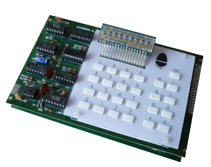

The Acorn System 1 or the Acorn Micro-Computer
The Acorn System 1 was an early 8-bit computer kit for hobbyists. It was based on the MOS 6502 Architecture and manufactured by Acorn starting 1979. The main design was done by the Cambridge-undergraduate student Sophie Wilson, and the cassette interface was designed by Steve Furber. This was Acorn's first computer.
Features
- Seven segment LED display
- 25 hexadecimal and function keys
- Cassette CUTS interface
- 6502 CPU running at 1MHz
- INS8154 RAMIO integrated circuit
- 2x2114 1024x4 RAM chips
- 2x74S571 512x4 PROM chip
- Optional INS8154 RAMIO Expansion Chip
- Socket for optional additional ROM or EEPROM
- 7.5V external power supply, 5V on-board regulator
- Two stacked circuit boards connected by a semi-flexible multi-conductor cable (Spectra Strip)
Acorn System VDU board
The Acorn Visual Display Unit Controller Board connects to the Standard Acorn Computer Bus and contains a memory mapped character storage R.A.M. which is transparently written to or read from by the C.P.U.
An MC6845 programmable controller I.C. provides all the synchronisation signals to drive a 625 line 50 fields per second V.D.U. together with read addresses for the character R.A.M. Characters are then fed to an SAA5050 character generator IC which produces the necessary dot patterns to create the characters to refresh the V.D.U.
The SAA5050 produces Teletext standard characters and has Red, Green and Blue drive outputs giving coloured characters or graphics.
The R.G.B. and sync outputs may be used to drive a colour encoder and modulator for a U.H.F. Television; There is also a 1 volt/75 ohm composite sync and video output which can directly drive a Monochrome Monitor on which the different colours will appear as different scales of grey.
The VDU board came with listings for programs which set up the MC6845, display 25 instructions in hex on the V.D.U. (with double or treble byte instructions on a single line) and allow the drawing of graphics or characters on the V.D.U. These programs may be loaded and run using the Acorn System 1 Monitor. Later new monitor ROM was able to link the VDU and an ASC 11 keyboard to Acorns' 4K Fast BASIC.
The versatility of the programmable MC6845 and the SAA5050 combination may be employed to give other screen formats e. g. 80 characters x 16 lines and double height characters. Thus the Acorn VDU was of great value to experimenters and producers of specialist display systems. The VDU controller PCB was supplied in kit form with a full set of I.C. sockets. It was easily assembled using a small soldering iron and useful hints on assembly may be found in the Acorn Micro-computer System 1 Technical Manual. The board operates from a single +5v supply from which it draws not more than 500 mA.
CPU - The Motorola 6502
The 6502 is an 8-bit MicroProcessor designed by MOS Technology. The team was led by Chuck Peddle and had also worked on the Motorola 6800. The 6502 is a simplified, but faster and cheaper design than the 6800.
The 6502 was introduced in 1975 and was the cheapest microprocessor on the market. Together with the Zilog Z80, the 6502 helped start the home computer revolution of the 1980s. The 6502 was used in a wide range of devices: the Atari 2600, the 8-bit Atari home computers, the Apple II, the Nintendo Entertainment System, the Commodore 64, the BBC Micro and many others. All used the 6502 or a variation of it.
The 6502 is a 1MHz design, while the 6502A is designed for 2MHz. The 6502A is 100% compatible with the original 6502.
Commodore soon bought MOS Technology, but conitnued to sell the microprocessor to competitors and licensed the design to other manufacturers.
Source: WikiPedia - MOS Technology 6502The 650x Instruction Set
| Mnemonic | Operation | Description |
|---|---|---|
| ADC | Add with Carry | Adds a memory location and the carry bit to the accumulator. |
| AND | Logical AND | Performs a logical AND between memory and the accumulator. |
| ASL | Arithmetic Shift Left | Shifts all bits one position to the left (in memory or accumulator). |
| BCC | Branch on Carry Clear | Branches to a new address if the carry flag is clear (0). |
| BCS | Branch on Carry Set | Branches to a new address if the carry flag is set (1). |
| BEQ | Branch on Equal (Zero Set) | Branches to a new address if the zero flag is set (1). |
| BIT | Bit Test | Tests bits in memory with the accumulator without modifying the accumulator. |
| BMI | Branch on Minus | Branches to a new address if the negative flag is set (1). |
| BNE | Branch on Not Equal | Branches to a new address if the zero flag is clear (0). |
| BPL | Branch on Plus | Branches to a new address if the negative flag is clear (0). |
| BRK | Force Break | Forces an interrupt request and pushes status and PC to the stack. |
| BVC | Branch on Overflow Clear | Branches to a new address if the overflow flag is clear (0). |
| BVS | Branch on Overflow Set | Branches to a new address if the overflow flag is set (1). |
| CLC | Clear Carry Flag | Clears the processor carry flag. |
| CLD | Clear Decimal Mode | Clears the processor decimal mode flag. |
| CLI | Clear Interrupt Disable | Clears the interrupt disable flag, allowing maskable interrupts. |
| CLV | Clear Overflow Flag | Clears the processor overflow flag. |
| CMP | Compare Accumulator | Compares the contents of a memory location with the accumulator. |
| CPX | Compare X Register | Compares the contents of a memory location with the X register. |
| CPY | Compare Y Register | Compares the contents of a memory location with the Y register. |
| DEC | Decrement Memory | Subtracts one from the value held at a specified memory location. |
| DEX | Decrement X Register | Subtracts one from the X register. |
| DEY | Decrement Y Register | Subtracts one from the Y register. |
| EOR | Exclusive OR | Performs a logical Exclusive OR between memory and the accumulator. |
| INC | Increment Memory | Adds one to the value held at a specified memory location. |
| INX | Increment X Register | Adds one to the X register. |
| INY | Increment Y Register | Adds one to the Y register. |
| JMP | Jump | Sets the program counter to a new address. |
| JSR | Jump to Subroutine | Pushes the return address to the stack and jumps to a new address. |
| LDA | Load Accumulator | Loads a byte of memory into the accumulator. |
| LDX | Load X Register | Loads a byte of memory into the X register. |
| LDY | Load Y Register | Loads a byte of memory into the Y register. |
| LSR | Logical Shift Right | Shifts all bits one position to the right (in memory or accumulator). |
| NOP | No Operation | Performs no operation, consuming 2 machine cycles. |
| ORA | Logical Inclusive OR | Performs a logical OR between memory and the accumulator. |
| PHA | Push Accumulator | Pushes a copy of the accumulator onto the stack. |
| PHP | Push Processor Status | Pushes a copy of the status flags onto the stack. |
| PLA | Pull Accumulator | Pulls a byte from the stack into the accumulator. |
| PLP | Pull Processor Status | Pulls a byte from the stack into the processor status flags. |
| ROL | Rotate Left | Rotates all bits one position left through the carry flag. |
| ROR | Rotate Right | Rotates all bits one position right through the carry flag. |
| RTI | Return from Interrupt | Pulls the processor flags and program counter from the stack. |
| RTS | Return from Subroutine | Pulls the program counter from the stack and resumes execution. |
| SBC | Subtract with Carry | Subtracts memory and the inverse of the carry bit from the accumulator. |
| SEC | Set Carry Flag | Sets the processor carry flag. |
| SED | Set Decimal Flag | Sets the processor decimal mode flag. |
| SEI | Set Interrupt Disable | Sets the interrupt disable flag, preventing maskable interrupts. |
| STA | Store Accumulator | Stores the contents of the accumulator in memory. |
| STX | Store X Register | Stores the contents of the X register in memory. |
| STY | Store Y Register | Stores the contents of the Y register in memory. |
| TAX | Transfer Accumulator to X | Copies the current value of the accumulator into the X register. |
| TAY | Transfer Accumulator to Y | Copies the current value of the accumulator into the Y register. |
| TSX | Transfer Stack Pointer to X | Copies the current value of the stack pointer into the X register. |
| TXA | Transfer X to Accumulator | Copies the current value of the X register into the accumulator. |
| TXS | Transfer X to Stack Pointer | Copies the current value of the X register into the stack pointer. |
| TYA | Transfer Y to Accumulator | Copies the current value of the Y register into the accumulator. |