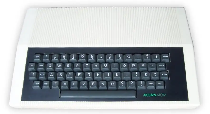

The Acorn Atom
The Acorn Atom was released in 1980 by Acorn Computers Ltd., and is the predecessor of the BBC Micro.
The computer was sold both as a kit or as a ready-assembled system. The main advantage over other systems of the time, was that the Acorn Atom had a high resolution graphics mode of 256x192 pixels, which was high for the cost of the system.
The Atom was based on the MOS Technology 6502 CPU and came with 2KByte of RAM that was expandable to 12K. With 2kByte of RAM, only 512 bytes were available for programs. 512 bytes were needed for Video RAM, and the other 1KByte was needed for the special Block Zero RAM that the 6502 architecture uses like other processors use registers, stack and other CPU variables.
If you wanted to use the high resolution graphcis, A video RAM expansion was needed. The screen memory could be upgraded to 6KByte. The machine featured an MC6847 Video Display Generator that allowed for text and graphics modes. The machine could be hooked up to a Television set or a monitor. The MC6847 was only capable of producing a 60Hz signal, which was incompatible with the European 50Hz PAL TV norm, and initially this prevented the machine from being used on many european TVs. Later Acorn produced a 50Hz PAL color card to fix this issue. (See below).
The Atom had an MC6847 Video Display Generator (VDG) video chip, allowing for both text and graphics modes. It could be connected to a TV or modified to output to a video monitor. Six video modes were available, with resolutions from 64x64 in 4 colours, up to 256x192 in monochrome. At the time, 256x192 was considered to be high resolution.
The built in BASIC version also had an assembler integrated into it, which allowed the programmer to freely use 6502 assembler in BASIC. The Atom's BASIC was developed by Sophie Wilson, and was not easy to use due to the oddities that it used compared to other popular BASIC versions. In 1982 Acorn released an upgrade board that allowed users to use the more advanced BBC Basic, that was developed for the BBC Micro.
The Acorn Atom Color Encoder board was designed to enable the use of the Acorn Atom computer on PAL television sets. It was sold as a peripheral but a version of the Atom was also sold with the board pre-installed. The board included:
- A 60-50 Hz converter
- RGB and Sync outputs
- Color encoded signal for the Atom's onboard modulator
- Red, Green, Blue, Yellow
- Yellow(Buff), Cyan, Magenta, Orange
Video - Motorola MC6847 VDG
The Motorola MC6847 is a versatile Video Display Generator (VDG) introduced in 1978, designed to interface between microprocessors and television circuitry. It was a staple of early 8-bit computing, most notably powering the TRS-80 Color Computer and the Dragon 32/64 The chip is capable of generating both alphanumeric text and bitmapped graphics in several distinct modes, utilizing an internal ROM for character generation or external RAM for high-resolution graphics. It outputs a composite video signal in NTSC format, though variants like the MC6847Y and MC6847P were used for different clocking and signal requirements.
Hardware Interface and Signal Logic
The MC6847 operates on a 3.579545 MHz clock—the standard NTSC colorburst frequency—which it uses to derive all internal timing for horizontal and vertical synchronization. It features an 8-bit data bus and a series of mode-select pins (GM0, GM1, GM2, S/A, Int/Ext, CSS that determine the display format. Because the VDG and the CPU (often the MC6809) must share access to the same bank of video RAM, the chip provides a Device Busy (DB) signal or works in tandem with a synchronous address multiplexer (like the MC6883 SAM) to prevent "snow" or bus contention during the active display cycle.
Alphanumeric and Semigraphics Modes
In its base Alphanumeric mode, the MC6847 displays a 32x16 grid of characters. It features an internal character generator ROM that produces a limited 5x7 pixel font within an 8x12 pixel block. A unique feature of this chip is its Semigraphics modes (SG4, SG6, SG8, SG12, etc.), which divide each character block into smaller "pixels" or sub-blocks. For instance, Semigraphics 4 divides a block into a 2x2 matrix, allowing for a pseudo-graphics resolution of 64x32 while still treating the data as ASCII-like character bytes, which significantly reduces the memory overhead for the host system.
High-Resolution Graphics and Color Palette
The chip’s true bitmapped graphics modes, referred to as "Full Graphics," range from Resolution Graphics One (RG1) at 64x64 pixels to High-Resolution Graphics Six (RG6) at 256x192 pixels. At its highest resolution, the MC6847 is limited to a monochrome (two-color) display due to the 6KB memory ceiling of the addressing scheme. In lower-resolution modes, such as 128x192, it supports a four-color palette. The color selection is governed by the Color Set Select (CSS) pin, which toggles between two hardware-defined palettes:
- Palette 0: Green, Yellow, Blue, Red.
- Palette 1: Buff (White), Cyan, Magenta, Orange.
Memory Addressing and Video Synthesis
The MC6847 does not have internal RAM; instead, it generates a 13-bit address bus (DA0–DA12 to fetch data from external memory. As the electron beam scans the television screen, the VDG continuously cycles through the memory locations, converting the retrieved bytes into a serial bitstream. This stream is then processed by the internal luminance (Y) and chrominance (phi-A, phi-B) modulators. Because the chip was designed for cost-effective home electronics, it handles the complex task of NTSC color encoding internally, requiring only a minimal external buffer and an RF modulator to produce a signal a standard television can interpret.
CPU - The Motorola 6502
The 6502 is an 8-bit MicroProcessor designed by MOS Technology. The team was led by Chuck Peddle and had also worked on the Motorola 6800. The 6502 is a simplified, but faster and cheaper design than the 6800.
The 6502 was introduced in 1975 and was the cheapest microprocessor on the market. Together with the Zilog Z80, the 6502 helped start the home computer revolution of the 1980s. The 6502 was used in a wide range of devices: the Atari 2600, the 8-bit Atari home computers, the Apple II, the Nintendo Entertainment System, the Commodore 64, the BBC Micro and many others. All used the 6502 or a variation of it.
The 6502 is a 1MHz design, while the 6502A is designed for 2MHz. The 6502A is 100% compatible with the original 6502.
Commodore soon bought MOS Technology, but conitnued to sell the microprocessor to competitors and licensed the design to other manufacturers.
Source: WikiPedia - MOS Technology 6502The 650x Instruction Set
| Mnemonic | Operation | Description |
|---|---|---|
| ADC | Add with Carry | Adds a memory location and the carry bit to the accumulator. |
| AND | Logical AND | Performs a logical AND between memory and the accumulator. |
| ASL | Arithmetic Shift Left | Shifts all bits one position to the left (in memory or accumulator). |
| BCC | Branch on Carry Clear | Branches to a new address if the carry flag is clear (0). |
| BCS | Branch on Carry Set | Branches to a new address if the carry flag is set (1). |
| BEQ | Branch on Equal (Zero Set) | Branches to a new address if the zero flag is set (1). |
| BIT | Bit Test | Tests bits in memory with the accumulator without modifying the accumulator. |
| BMI | Branch on Minus | Branches to a new address if the negative flag is set (1). |
| BNE | Branch on Not Equal | Branches to a new address if the zero flag is clear (0). |
| BPL | Branch on Plus | Branches to a new address if the negative flag is clear (0). |
| BRK | Force Break | Forces an interrupt request and pushes status and PC to the stack. |
| BVC | Branch on Overflow Clear | Branches to a new address if the overflow flag is clear (0). |
| BVS | Branch on Overflow Set | Branches to a new address if the overflow flag is set (1). |
| CLC | Clear Carry Flag | Clears the processor carry flag. |
| CLD | Clear Decimal Mode | Clears the processor decimal mode flag. |
| CLI | Clear Interrupt Disable | Clears the interrupt disable flag, allowing maskable interrupts. |
| CLV | Clear Overflow Flag | Clears the processor overflow flag. |
| CMP | Compare Accumulator | Compares the contents of a memory location with the accumulator. |
| CPX | Compare X Register | Compares the contents of a memory location with the X register. |
| CPY | Compare Y Register | Compares the contents of a memory location with the Y register. |
| DEC | Decrement Memory | Subtracts one from the value held at a specified memory location. |
| DEX | Decrement X Register | Subtracts one from the X register. |
| DEY | Decrement Y Register | Subtracts one from the Y register. |
| EOR | Exclusive OR | Performs a logical Exclusive OR between memory and the accumulator. |
| INC | Increment Memory | Adds one to the value held at a specified memory location. |
| INX | Increment X Register | Adds one to the X register. |
| INY | Increment Y Register | Adds one to the Y register. |
| JMP | Jump | Sets the program counter to a new address. |
| JSR | Jump to Subroutine | Pushes the return address to the stack and jumps to a new address. |
| LDA | Load Accumulator | Loads a byte of memory into the accumulator. |
| LDX | Load X Register | Loads a byte of memory into the X register. |
| LDY | Load Y Register | Loads a byte of memory into the Y register. |
| LSR | Logical Shift Right | Shifts all bits one position to the right (in memory or accumulator). |
| NOP | No Operation | Performs no operation, consuming 2 machine cycles. |
| ORA | Logical Inclusive OR | Performs a logical OR between memory and the accumulator. |
| PHA | Push Accumulator | Pushes a copy of the accumulator onto the stack. |
| PHP | Push Processor Status | Pushes a copy of the status flags onto the stack. |
| PLA | Pull Accumulator | Pulls a byte from the stack into the accumulator. |
| PLP | Pull Processor Status | Pulls a byte from the stack into the processor status flags. |
| ROL | Rotate Left | Rotates all bits one position left through the carry flag. |
| ROR | Rotate Right | Rotates all bits one position right through the carry flag. |
| RTI | Return from Interrupt | Pulls the processor flags and program counter from the stack. |
| RTS | Return from Subroutine | Pulls the program counter from the stack and resumes execution. |
| SBC | Subtract with Carry | Subtracts memory and the inverse of the carry bit from the accumulator. |
| SEC | Set Carry Flag | Sets the processor carry flag. |
| SED | Set Decimal Flag | Sets the processor decimal mode flag. |
| SEI | Set Interrupt Disable | Sets the interrupt disable flag, preventing maskable interrupts. |
| STA | Store Accumulator | Stores the contents of the accumulator in memory. |
| STX | Store X Register | Stores the contents of the X register in memory. |
| STY | Store Y Register | Stores the contents of the Y register in memory. |
| TAX | Transfer Accumulator to X | Copies the current value of the accumulator into the X register. |
| TAY | Transfer Accumulator to Y | Copies the current value of the accumulator into the Y register. |
| TSX | Transfer Stack Pointer to X | Copies the current value of the stack pointer into the X register. |
| TXA | Transfer X to Accumulator | Copies the current value of the X register into the accumulator. |
| TXS | Transfer X to Stack Pointer | Copies the current value of the X register into the stack pointer. |
| TYA | Transfer Y to Accumulator | Copies the current value of the Y register into the accumulator. |
RAM max: 12kB
VRAM: 512B
128x96 mono
64x192 2 color
128x192 2 color
256x192 mono