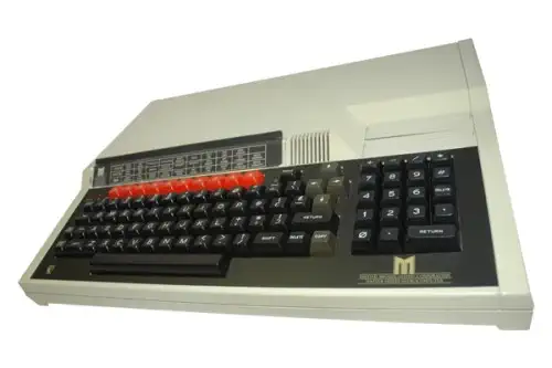

BBC Master 512
The BBC Master 512 had 512 kByte of RAM and a 10MHz Intel 80186 co-processor card. This enabled the system to run DOS Plus, and the GEM Graphical User Interface. The co-processor card was also introduced as an upgrade to the BBC Master 128 also, for a reduced price. There were compatibility issues with various DOS applications, which constrained the system. The memory requirement of the GEM ui was also a constraint and caused problems with some applications. These could be helped with memory expansion modules. DOS was only supported up to version 2.1, later versions of DOS were not supported officially and could cause software not to work.
The Master 512 expansion added a plug-in second processor board containing an Intel 80186 and 512 KB of RAM. When this board was in control, the 65C12 was effectively sidelined — the 80186 took over as the active CPU, running DOS Plus and BBC BASIC (86).
Sound on the Master Series
Like on the original BBC Master, this computer continued to use the Texas Instruments SN76489 as its primary sound generator, maintaining 100% downward compatibility with software written for the Model B. However, the Master featured a more complex internal architecture that changed how the chip was accessed and how sound was routed.
Integration and Internal Routing
In the BBC Master, the SN76489 was no longer an entirely "standalone" component in the same way it was on the Model A/B motherboards. It was integrated into the System VIE (Versatile Interface Adapter) logic. While the registers and programming remained identical, the sound output was mixed with the optional internal speech synthesis hardware (the Tms5220 and its associated TMS6100 ROMs). This allowed the Master to blend standard PSG (Programmable Sound Generator) tones with high-quality synthesized speech and "phonemes."
BBC Master Series
- ECO-Net connector
- Audio Out
- Cassette port
- RS 432 communications port
- Analoge port
- RGB Monitor connector
- Composite Video connector
- RF Output for TV
BBC Master Models
The BBC Master was produced in a few variations. Not all were produced in large quantities, and some of them are hard to find.
- Master 128 - First model of the Master series
- Master Turbo - Featured a 65C102 co-processor @4MHz
- Master AIV - Master Turbo with a SCSI interface and a Videodisc
- Master ET - For use on a network, only had RGB and Econet connectors
- Master 512 - Intel 80186 co-processor @ 10MHz to run DOS Plus and GEM
- Master Scientific - Prototype, NS32016 co-processor @ 8MHz
- Master Compact - Compact version of the 128
Motorola MC6845 Video Display Generator
The Motorola MC6845 commonly referred to as a CRTC (Cathode Ray Tube Controller) served as the architectural backbone for the video subsystems of many iconic 8-bit computers, including the IBM PC (CGA/MDA) and the BBC Micro. Unlike modern GPUs that handle complex rendering, the MC6845 was a programmable timing generator. Its primary function was to manage the synchronization signals (HSYNC and VSYNC) and generate the memory addresses required to fetch pixel or character data from video RAM. By offloading these repetitive timing tasks from the CPU, it allowed for flexible display formats through a set of 18 internal 8-bit registers.
At its core, the chip operates using a series of internal counters that track the horizontal and vertical position of the electron beam. The programmer defines the display geometry by writing to registers that control the total number of horizontal characters, the horizontal displayed characters, and the sync pulse widths. This programmability allowed developers to implement various "tricks," such as hardware scrolling or split-screen effects, by manipulating the Start Address Register (R12 and R13) mid-frame. This changed which part of the video memory the controller pointed to at the beginning of a raster scan.
The interface between the MC6845 and the system memory is fundamentally passive regarding data content. The controller outputs a Memory Address (MA0–MA13) and Row Address (RA0–RA4) but it does not actually "see" the data being fetched. In a typical character-mapped configuration, the MA lines point to the character code in RAM, while the RA lines determine which specific scanline of that character is being pulled from a Font ROM. This separation of concerns made it highly versatile, supporting both alphanumeric modes and "all-points-addressable" (APA) graphics modes depending on how the external logic interpreted the address lines.
Timing and synchronization are governed by the Character Clock (CLK) input, which increments the internal horizontal counter. To prevent "snow" or visual artifacts, the system must carefully manage bus contention between the CPU and the MC6845, as both require access to the video RAM. This was often solved using "interleaved" access, where the CPU and CRTC traded cycles, or by restricting CPU writes to the vertical blanking interval. The chip's ability to provide a Light Pen strobe input further expanded its utility, allowing the hardware to latch the current memory address when a light pen hit was detected, providing a primitive but effective form of user interaction.
Programming the MC6845 Video Display Generator
To program the MC6845 for a specific resolution, you must calculate the values for its internal registers based on your system's Character Clock (CLK) and the target monitor's refresh rates. The chip operates by counting character units rather than individual pixels, so your first step is determining how many pixels wide a "character" is (typically 8) to find your horizontal frequency.
1. Horizontal Timing Registers (R0–R3)
These registers define the width of the scanline and the position of the horizontal sync pulse (HSYNC).- R0 (Horizontal Total): The total number of character clocks in a full scanline, including the visible area and the "overscan/blanking" period.
- R1 (Horizontal Displayed): The number of characters actually shown on the screen (e.g., 40 or 80).
- R2 (Horizontal Sync Position): This determines where the sync pulse starts. Moving this value shifts the entire image left or right on the monitor.
- R3 (Sync Width): Defines the duration of the HSYNC pulse in character clock units.
2. Vertical Timing Registers (R4–R7)
Vertical timing is measured in character rows not individual scanlines.- R4 (Vertical Total): The total number of character rows in a frame.
- R5 (Vertical Total Adjust): A "fine-tuning" register that adds a specific number of scanlines to the end of a frame to reach exactly 50Hz or 60Hz if the character rows don't divide perfectly.
- R6 (Vertical Displayed): The number of visible rows on the screen (e.g., 25).
- R7 (Vertical Sync Position): Determines the vertical start of the sync pulse, effectively moving the image up or down.
3. Character and Scanline Control (R9–R11)
The MC6845 needs to know the physical "height" of your characters to correctly increment its addresses.- R9 (Maximum Scan Line Address): This tells the chip how many scanlines make up one character row (e.g., 7 for an 8-pixel high character, as the count starts at 0).
- R10 & R11 (Cursor Control): These define which scanlines within a character block the cursor occupies and whether it should blink.
4. Memory Mapping (R12–R13)
These are the Start Address Registers They determine which byte in your Video RAM corresponds to the very first character at the top-left of the screen. By changing these values during a "Vertical Blank" period, you can achieve Hardware Scrolling If you increment the start address by the width of one row, the screen appears to jump up instantly without the CPU having to move a single byte of data in memory.BBC Master Operating System (MOS)
The Master Operating System (MOS) was the firmware at the core of the BBC Master series, stored in ROM alongside BBC BASIC IV. It evolved directly from the BBC Micro’s MOS but extended its feature set to support the larger memory map, extra ROM sockets, and co-processor options of the Master family. The MOS provided the low-level routines for device I/O, screen and keyboard handling, interrupt servicing, and the command-line interface (*commands). Unlike many contemporary 8-bit microcomputer OSes, the MOS emphasized modularity: ROM-based language interpreters, filing systems, and utilities could be slotted in and invoked seamlessly through a standardized API.
Technically, the Master MOS ran on the 65C12 processor and occupied the upper section of the 16-bit address space, mapped into the top 16 KB of memory. It made heavy use of vectored entry points, with the “OSWORD,” “OSBYTE,” and “OSCLI” calls forming the backbone of its application programming interface. This vector-based approach allowed extensions and filing systems to hook into the OS without patching or breaking existing code. The MOS also provided bank-switching support to take advantage of the Master’s expanded RAM (up to 512 KB in some models) and integrated utilities like the “EDIT” ROM and View family of applications.
A critical innovation in the Master MOS was its coordination with the Tube interface, Acorn’s high-speed second-processor link. When a co-processor such as the 80186 board (in the Master 512) or the 65C102 second processor was active, the MOS suspended most of its local duties and became a host interface layer, forwarding I/O and OS calls between the host hardware and the second processor. This design let the Master run different CPUs and operating environments while maintaining compatibility with MOS services. The Master MOS thus acted as both a conventional 8-bit OS and a hardware abstraction layer, making it one of the more sophisticated firmware environments in the 8-bit era.
BBC Basic Language and OS
BBC BASIC was a high-level programming language created by Acorn Computers in 1981 for the BBC Microcomputer System, commissioned by the BBC Computer Literacy Project. It was based on the earlier Dartmouth BASIC but extended with structured programming features and inline assembler support, making it both beginner-friendly and powerful for advanced users. Unlike many contemporary BASIC dialects, BBC BASIC emphasized readability, supporting named procedures and functions, local variables, and full IF...THEN...ELSE constructs, which helped foster good programming practice among students and hobbyists.
One of the most distinctive aspects of BBC BASIC was its ability to integrate 6502 assembly language directly within BASIC source code. This meant programmers could write performance-critical routines in machine code without leaving the BASIC environment, a feature that was far ahead of its time. Combined with the BBC Micro’s flexible graphics and sound capabilities, BBC BASIC provided a complete toolkit for educational, scientific, and entertainment applications, spanning simple text-based teaching programs to advanced arcade-style games.
BBC BASIC survived long beyond the BBC Micro itself. Versions were ported to CP/M, MS-DOS, RISC OS, Windows, and even modern platforms like iOS and Android through interpreters and emulators. Its legacy lies not only in its technical innovations but also in its cultural impact: an entire generation of UK students learned programming principles through BBC BASIC. Below is a simple code sample that demonstrates its syntax clarity and structure:
  10 REM BBC BASIC with inline 6502 assembly

  20 DIM code 20

  30 FOR pass = 0 TO 2

  40   P% = code

  50   [OPT pass

  60   LDA &70      \ Load value from memory location &70

  70   CLC          \ Clear carry

  80   ADC #1       \ Add 1

  90   STA &70      \ Store back to &70

 100   RTS          \ Return to BASIC

 110   ]

 120 NEXT

 130 ?&70 = 0       \ Initialize memory location to 0

 140 CALL code      \ Call machine code routine

 150 PRINT "Value now = "; ?&70

 160 CALL code

 170 PRINT "Value now = "; ?&70

 180 END
BBC Basic (86) Language
BBC Basic (86) was not the standard BBC Basic that shipped with the BBC Micro and the BBC Master series.
Acorn provided BBC Basic ported to the Z80/8086 family of CPU's as BBC Basic (86). This version of BBC Basic preserved the language features and structure of the original BBC Basic, but was re-engineered to run natively on the x86 processor under DOS Plus.
The language was compatible with the original BBC Basic, execpt for programs that relied on integratign 6502 Assembly inline code directly. This kept the educational and structured programming strengths of the language intact.
BBC Basic IV (6502)
-
Processor & Environment
Runs natively on the 6502 inside the BBC Master 128. It is stored in ROM, so the machine boots directly into the BASIC prompt. -
Assembly Integration
One of its standout features was the ability to inline 6502 assembly language within BASIC source code, assembled on the fly and callable from BASIC. This gave programmers direct access to the BBC Micro/Master’s hardware. -
Graphics & Sound
Tight integration with the BBC’s Video ULA and sound hardware. Commands like MODE, PLOT, and SOUND directly controlled the display and audio. -
Compatibility
Could run virtually all software written for BBC Micro BBC BASIC (III and earlier), while also adding structured enhancements such as local variables in procedures and functions.
BBC Basic (86)
-
Processor & Environment
Designed for the Intel 80186 co-processor of the BBC Master 512. It ran under Digital Research DOS Plus (a CP/M-86/MS-DOS–like OS), so it was a disk-loaded program rather than a ROM-resident interpreter. -
Assembly Integration
Instead of inline 6502 code, BBC BASIC (86) supported embedding x86 machine code. Programmers could assemble and execute Intel instructions within BASIC programs, preserving the hybrid high/low-level design philosophy. -
System Access
Lacked the direct, built-in graphics and sound primitives of the 6502 version, since it ran in a DOS-like environment without the BBC Micro’s memory-mapped hardware. However, DOS calls and CP/M BIOS services could be accessed from BASIC. -
Compatibility
Mostly source-compatible with earlier BBC BASIC, but programs relying on graphics, sound, or 6502-specific assembly had to be adapted. Purely text/logic-heavy code would usually run without modification.
BBC BASIC IV was a tightly integrated environment optimized for the BBC Master’s native hardware, while BBC BASIC (86) extended the language into the world of Intel processors and DOS-style operating systems. Both retained the structured programming enhancements that set BBC BASIC apart, but their hardware reach and inline assembly capabilities reflected their respective architectures — one bound to the BBC’s custom ULA and 6502, the other living in a more generic DOS environment on the 80186.
CPU - CMOS 65C02 family (6502 Compatible)
The 65C02 family of CPU's, is binary compatible with the NMOS 6502 instruction set, but it is an enhanced CMOS implementation. The CPU fixes some NMOS 6502 hardware bugs (such as the infamous indirect JMP page-wrap anomaly), reduces power consumption, and adds cycle-accurate “illegal” instruction handling (undefined opcodes are removed). There are different implementations of the 65C02 family. For instance there is the Synerteck SY65SC12 variant, which integrates a synchronous clock generator and typically runs at higher clock rates (up to 14 MHz in some grades) compared to MOS’s 1–2 MHz NMOS parts. Internally, the CMOS design gives fully static operation (the clock can be halted without data loss), adds new instructions (e.g., STZ, TRB, TSB, INC A, DEC A, BRA), and supports expanded addressing modes such as (ZP) indirect addressing. Electrically, it requires CMOS-level signals and produces lower heat dissipation. In short: it will run existing 6502 code unchanged, but behaves more predictably, consumes less power, and provides extra opcodes and addressing options not present in the original MOS NMOS 6502 (STZ, TSB, TRB, INC A, DEC A, BRA, etc.)
The 65C02 is not pin fully compatible with the 6502 CPU. The 65C02 family redefined some pins from the original 6502 design. For instance the S0 pin is not present, and some CMOS implementations have VPB and MLP pins. Depending on the exact pin usage, it is sometimes possible to use a 65C02 in a 6502 socket, but in most cases, the two CPU's are not pin compatible as bus timing and electrical characteristics differe from the NMOS 6502.
CPU - The Intel 80186
The Intel 80186, introduced in 1982, was a 16-bit microprocessor derived from the earlier 8086 architecture. It was designed not only as a CPU but also as a highly integrated solution for embedded and specialized systems. To this end, the 80186 incorporated on-chip peripherals such as interrupt controllers, timers, a DMA controller, and clock generator circuitry — functions that previously required separate support chips. This integration made it attractive for cost-sensitive applications like industrial controllers, communications hardware, and certain personal computer variants.
Architecturally, the 80186 was fully compatible with the 8086 instruction set, while offering a small set of new instructions and microarchitectural improvements that reduced the number of clock cycles needed for many operations. It maintained a 20-bit address bus, allowing access to 1 MB of memory, and a 16-bit data bus. Performance enhancements over the 8086 included faster multiply and divide instructions, as well as new string and bit-manipulation instructions. Despite these improvements, the chip was not widely adopted in mainstream IBM PC compatibles because the integrated peripherals conflicted with the way IBM’s hardware was organized.
The 80186 found its niche in embedded systems, but it also appeared in a handful of personal computers, such as the BBC Master 512, the Siemens PC-D, and the Tandy 2000. These systems benefited from the processor’s efficiency and built-in features, but software compatibility issues with standard PC designs limited their commercial success. Nevertheless, the 80186 influenced later designs, and its embedded-oriented variant, the 80188 (with an 8-bit data bus), enjoyed long life in control systems well into the 1990s. The 80186 represents Intel’s transitional step between the general-purpose 8086 and the more standardized, performance-driven 80286 that followed.
optional Intel 80186 or 65C102
1 noise generator
16 volume levels.
320x256 4 colors
160x256 8 colors
DOS Plus (optional)