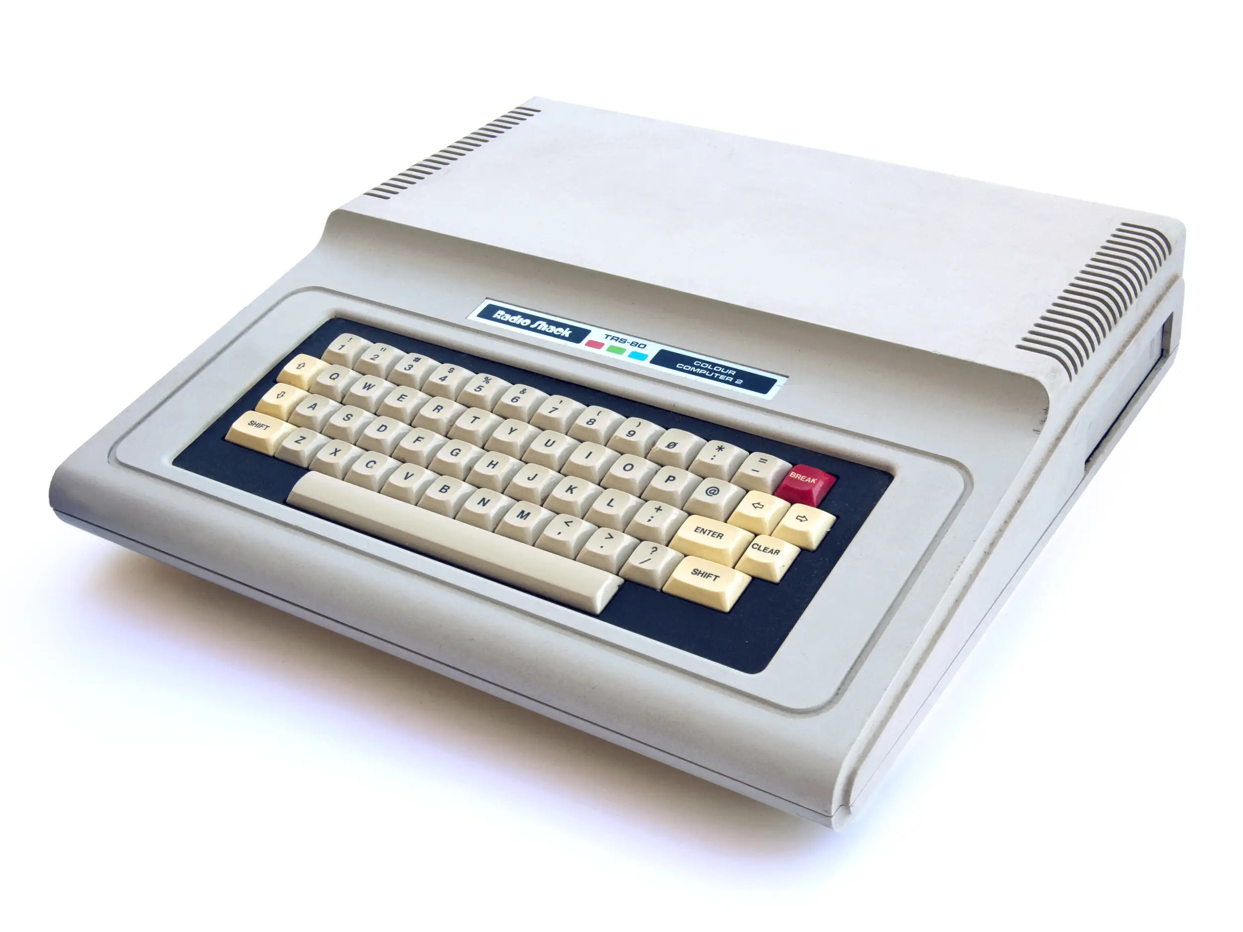

TRS80 Color Computer 2
The TRS 80 Color Computer 2, or popularly the CoCo 2, was introduced in 1983 as a replacement for the first CoCo, which was now known as the CoCo 1. The CoCo 2 has the same characteristics as the CoCo 1 but is equipped with a better keyboard and more integrated circuitry.
Several models of the CoCo 2 were produced, with increasing RAM capacities. The original version came with 8K RAM, but later the machine was provided with 16, 32 and finally 64K of RAM.
The CoCo 2 runs on the Motorola 6809E processor clocked at 0.89MHz. By programming the clock generator, speeds of 1.8MHz could be achieved.
Expansion Ports:
- Expansion/Cartridge port
- Two analog joystick connectors
- Cassette Interface, 1500 baud
- RS232 Serial port
- RF TV connector
CPU - The Motorola 6809
The Motorola 6809 is an 8-bit microprocessor with some 16-bit features. It was designed by Motorola's Terry Ritter and Joel Boney and introduced in 1978. Although source compatible with the earlier Motorola 6800, the 6809 offered significant improvements over it and 8-bit contemporaries like the MOS Technology 6502, including a hardware multiplication instruction, 16-bit arithmetic, system and user stack registers allowing re-entrant code, improved interrupts, position-independent code and an orthogonal instruction set architecture with a comprehensive set of addressing modes.
Video - Motorola MC6847 VDG
The Motorola MC6847 is a versatile Video Display Generator (VDG) introduced in 1978, designed to interface between microprocessors and television circuitry. It was a staple of early 8-bit computing, most notably powering the TRS-80 Color Computer and the Dragon 32/64 The chip is capable of generating both alphanumeric text and bitmapped graphics in several distinct modes, utilizing an internal ROM for character generation or external RAM for high-resolution graphics. It outputs a composite video signal in NTSC format, though variants like the MC6847Y and MC6847P were used for different clocking and signal requirements.
Hardware Interface and Signal Logic
The MC6847 operates on a 3.579545 MHz clock—the standard NTSC colorburst frequency—which it uses to derive all internal timing for horizontal and vertical synchronization. It features an 8-bit data bus and a series of mode-select pins (GM0, GM1, GM2, S/A, Int/Ext, CSS that determine the display format. Because the VDG and the CPU (often the MC6809) must share access to the same bank of video RAM, the chip provides a Device Busy (DB) signal or works in tandem with a synchronous address multiplexer (like the MC6883 SAM) to prevent "snow" or bus contention during the active display cycle.
Alphanumeric and Semigraphics Modes
In its base Alphanumeric mode, the MC6847 displays a 32x16 grid of characters. It features an internal character generator ROM that produces a limited 5x7 pixel font within an 8x12 pixel block. A unique feature of this chip is its Semigraphics modes (SG4, SG6, SG8, SG12, etc.), which divide each character block into smaller "pixels" or sub-blocks. For instance, Semigraphics 4 divides a block into a 2x2 matrix, allowing for a pseudo-graphics resolution of 64x32 while still treating the data as ASCII-like character bytes, which significantly reduces the memory overhead for the host system.
High-Resolution Graphics and Color Palette
The chip’s true bitmapped graphics modes, referred to as "Full Graphics," range from Resolution Graphics One (RG1) at 64x64 pixels to High-Resolution Graphics Six (RG6) at 256x192 pixels. At its highest resolution, the MC6847 is limited to a monochrome (two-color) display due to the 6KB memory ceiling of the addressing scheme. In lower-resolution modes, such as 128x192, it supports a four-color palette. The color selection is governed by the Color Set Select (CSS) pin, which toggles between two hardware-defined palettes:
- Palette 0: Green, Yellow, Blue, Red.
- Palette 1: Buff (White), Cyan, Magenta, Orange.
Memory Addressing and Video Synthesis
The MC6847 does not have internal RAM; instead, it generates a 13-bit address bus (DA0–DA12 to fetch data from external memory. As the electron beam scans the television screen, the VDG continuously cycles through the memory locations, converting the retrieved bytes into a serial bitstream. This stream is then processed by the internal luminance (Y) and chrominance (phi-A, phi-B) modulators. Because the chip was designed for cost-effective home electronics, it handles the complex task of NTSC color encoding internally, requiring only a minimal external buffer and an RF modulator to produce a signal a standard television can interpret.
RAM max: 64kB
or single bit sound.
max 256x192 2 color mode